The MAX3420E Interrupt System - Maxim
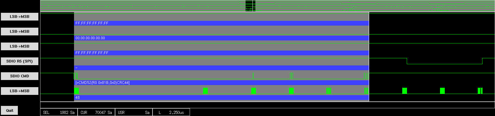
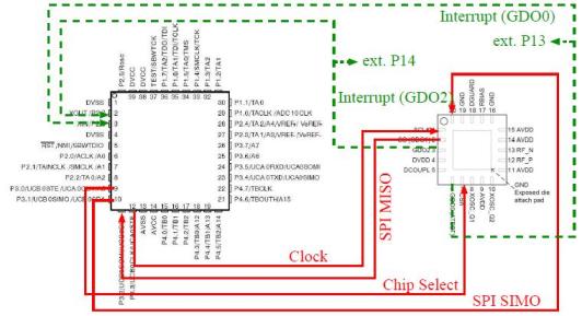
The MAX3420E adds USB Peripheral functionality to any SPI master such as a microcontroller. MAX3420E operation is largely defined by the interrupt request bits it . ->

Add USB to Anything - Maxim
This is an expanded draft of the article published in the July 2005 issue of . Therefore, an SPI interface with no interrupt support and a bidirectional data . ->

Serial Peripheral Interface Bus - Wikipedia, the free encyclopedia
Setting the SPI Interrupt Enable (SPIE) bit in the SPCR enables the inter . the SPI interrupt flag (SPIF) is set and the received byte is transferred to the . ->
AVR317: Using the Master SPI Mode of the USART module
. a circular buffer and interrupt-controlled communication. . (interrupt version) Initialize UART in Master SPI. Mode. Toggle SS line once to. synchronize slave . ->
Using the SPI protocol
2. The SPI Interrupt Flag (SPIF) in the SPI Status Register (SPSR) will be set. . master and the slave device the SPI interrupt flag (SPIF) is set and the . ->

LatticeMico32 SPI
trigger interrupt requests. The master SPI also has a slave-select register that . Slave interrupt request signal. Table 3: LatticeMico32 SPI I/O Port . ->

SPI
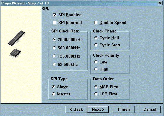
. do not need to turn on the SPI interrupt (SPIE bit) because sending a byte is . If you are setting up SPI between two MCUs, just set the clock polarity and . ->
C280x/C28x3x Hardware Interrupt
C280x SPI Receive. C280x SPI Transmit. Only one Hardware Interrupt block can be used in a model. . Each interrupt is represented by four parameters shown on . ->

23 Section 23. Serial Peripheral Interface
Each SPI module also has the following associated bits for interrupt control: . the software to enable/disable SPI interrupts when a new character is . ->
 |
 |
 |
 |
 |
 |
 |
 |